

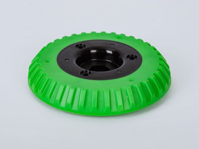
The first visible molding defect is often a late warning about a much earlier design decision. A sink mark beside a thick boss, an ejection scar on a cosmetic face, or a warped mounting edge can originate in geometry approved before tool steel was cut.
A pre-tooling review must therefore ask whether the part can fill, cool, release, and pass its real acceptance tests. Requests for custom injection molding services become substantially clearer when those questions are resolved before mold construction.
Define What a Good Part Must Do
A molded component is not judged solely by whether the mold cavity fills. Assembly loads, snap engagement, sealing, appearance, and dimensional stability determine which features require control. A designer may tolerate a minor witness line on a concealed rib but reject the same mark on a visible front panel. Functional, cosmetic, and measurement requirements should be separated before the tool concept is developed.
The drawing needs material designation, controlled dimensions, anticipated mating parts, and surface expectations. If the design includes threaded metal inserts, a living hinge, or a soft-grip region, those features affect tooling and processing from the beginning. Without clear acceptance criteria, an early sample may look acceptable while missing the characteristics that determine production approval.
Match Resin Behavior to Wall Geometry
Polymer selection and part shape cannot be reviewed independently. ABS, PP, PC, POM, PA66, and PEEK have different shrinkage, stiffness, moisture response, and processing demands. Reinforced grades add further considerations: filler content and flow direction can produce different shrinkage behavior along different axes.
A nominally precise cavity does not guarantee that the cooled molded part reproduces every dimension exactly. Moisture-sensitive resins may also need controlled conditioning before dimensional measurements from different sample batches can be meaningfully compared.
Abrupt wall-thickness changes can cause uneven cooling and local sinks, while excessively thin passages may restrict flow before the cavity is completely filled. Ribs and bosses should support the required load without creating large, isolated masses of plastic. Engineers seeking custom injection molding services need to confirm the intended resin and relevant dimensional conditions rather than assuming one generic wall rule applies to all materials.
Check Draft, Undercuts, and Ejection Paths
A cavity can reproduce complex geometry but still be unable to release the part without damage. Faces parallel to tool opening usually need suitable draft; textured surfaces may require special consideration because their microgeometry increases release resistance. Side openings, hooks, and undercuts may call for slides, lifters, collapsible cores, or a revised parting strategy.
Ejection forces need enough bearing area to avoid distortion and surface marks. Deep thin walls and rigid internal ribs can behave differently as the polymer cools, so the location of pins and parting lines should be evaluated against both function and appearance. Draft, cavity layout, and part-release strategy are assessed during internal mold design and toolmaking at Hanstar Technologies, before the first pieces reach inspection.
Resolve Gate Location and Cooling Before Cutting Steel
A gate introduces melt into the cavity, but its position also influences weld lines, flow length, appearance, and packing behavior. Placing it on a visible face may conflict with cosmetic requirements; placing it far from a thick section may complicate pressure distribution. Cooling channels then determine how consistently different regions lose heat during the molding cycle.
Mold-flow analysis can examine likely filling and cooling behavior before tooling is finalized, although its predictions still require confirmation in mold trials. A review of gate position and cooling forms part of the company’s DFM preparation, and its injection presses span a 50–500-ton range.
An appropriate discussion of custom injection molding services should distinguish tooling precision from molded-part tolerance: the company’s 0.005 mm moldmaking precision does not imply every finished plastic dimension meets that limit.
Use Mold Trials to Confirm the Specification
A mold trial reveals how the planned gate, cooling arrangement, and ejection system behave once actual material is processed. Inspection should address critical dimensions after appropriate conditioning, visible defects, insert placement, surface texture, and fit with mating components. Trials can expose the need to adjust processing conditions or, in some cases, revise the tool.
Acceptance standards should make the distinction between an adjustable molding condition and a geometry problem explicit. A repeatable inspection interval matters as well: dimensions recorded immediately after ejection may differ from those measured after cooling or conditioning. The project should define measurement timing, sample quantity, and inspection environment before the trial starts.
For molded components, Hanstar Technologies works with resins including PC/ABS, PBT, glass-filled PA66, and elastomers such as TPE or TPU. It also offers insert molding, overmolding, SPI or VDI surface finishes, and secondary operations such as ultrasonic welding, marking, and assembly.
Its typical molded-part tolerance is around ±0.02 mm, with application to any particular feature subject to the polymer and geometry. Recorded first-piece, in-process, and finished-part inspections can then support a consistent release decision.
Tooling approval should confirm a manufacturing route, not merely authorize the purchase of a mold. Hanstar Technologies combines mold design, toolmaking, injection production, and secondary operations. A request for a pre-tooling DFM review can specify the controlled model, the selected resin, and the functional and cosmetic characteristics that take priority.